The description below is presented twice since the fault counter behaves differently depending on what type of DTC that is being monitored. See the article Interpreting information in the Graph view for further information.
Unconfirmed DTC limit is +127
The description below is applicable when the Unconfirmed limit and the Failed limit are the same i.e. +127.
Figure description (number 1-12)
|
Fig. No. |
Description |
Fig. No. |
Description |
Fig. No. |
Description |
|---|---|---|---|---|---|
|
1 |
Failed limit. |
5 |
No result (test is stopped). |
9 |
Variable (e.g. signal) monitored by the test is correct. |
|
2 |
Unconfirmed limit. |
6 |
Fault not detected. |
10 |
Test started (test run criteria is fulfilled). Jump down to -128 when fault is not detected so many times that the test result Passed is reached. |
|
3 |
Passed limit. |
7 |
Variable (e.g. signal) monitored by the test is not correct. |
11 |
Jump up to +127 when fault is detected so many times that the test result Failed is reached. |
|
4 |
Fault detected. |
8 |
Gray zone. |
12 |
Jump down to - 128 when fault is not detected so many times that the test result Passed is reached. |
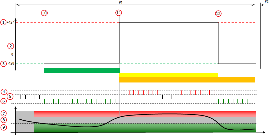


#1 - #2 in the figure represent control module operation cycles.
Unconfirmed DTC limit is less than +127
The description below is applicable when the Unconfirmed limit is less than the Failed limit i.e. less than +127.
Figure description (number 1-15)
|
Fig. No. |
Description |
Fig. No. |
Description |
Fig. No. |
Description |
|---|---|---|---|---|---|
|
1 |
Failed limit. |
6 |
Fault not detected. |
11 |
Jump up from negative values when fault is detected. |
|
2 |
Unconfirmed limit. |
7 |
Variable (e.g. signal) monitored by the test is not correct. |
12 |
Step up when fault is detected. |
|
3 |
Passed limit. |
8 |
Gray zone. |
13 |
Test is stopped (test run criteria is not fulfilled). |
|
4 |
Fault detected. |
9 |
Variable (e.g. signal) monitored by the test is correct. |
14 |
Test started (test run criteria is fulfilled). Step up when fault is detected. |
|
5 |
No result (test is stopped). |
10 |
Test started (test run criteria is fulfilled). Step down when fault is not detected. |
15 |
Jump down from positive values when fault is not detected. |
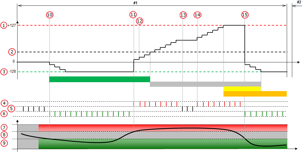

#1 - #2 in the figure represent control module operation cycles.