The description below is presented twice since the fault counter behaves differently depending on what type of DTC that is being monitored. See the article Interpreting information in the Graph view for further information.
Unconfirmed DTC limit is +127
The description below is applicable when the Unconfirmed limit and the Failed limit are the same i.e. +127. Please refer to the article Interpreting the Fault counter for further details about the Fault counter.
Figure description (number 1-4)
|
Fig. No. |
Description |
|---|---|
|
1 |
Confirmed limit |
|
2 |
Failed limit |
|
3 |
Passed limit |
|
4 |
Aged limit |
Calibration parameters in figure (number 1 and 4)
|
Calibration parameter |
Description |
|---|---|
|
Confirmed limit |
Number of consecutive control module operation cycles in which the fault counter reach the Failed limit (at least once) until the DTC is confirmed. See fig. no. 1. |
|
Failed inhibited |
N/A |
|
Unconfirmed limit |
N/A |
|
Aged limit |
Number of consecutive control module operation cycles in which the fault counter reach the Passed limit (at least once) and never the Failed limit until the DTC is aged. See fig. no. 4. |
|
Step up |
N/A |
|
Step down |
N/A |
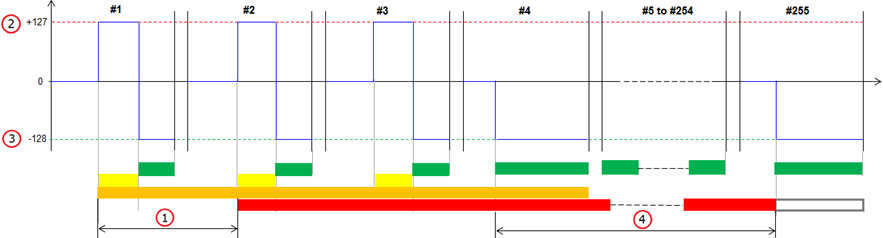


#1 - #255 in the figure represent control module operation cycles.
Unconfirmed DTC limit is less than +127
The description below is applicable when the Unconfirmed limit is less than the Failed limit i.e. less than +127. Please refer to the article Interpreting the Fault counter for further details about the Fault counter.
Figure description (number 1-8)
|
Fig. No. |
Description |
|---|---|
|
1 |
Confirmed limit |
|
2 |
Failed limit |
|
3 |
Unconfirmed limit |
|
4 |
Aged limit |
|
5 |
Step up |
|
6 |
Step down |
|
7 |
Passed limit |
|
8 |
Aged limit |
Calibration parameters in figure (number 1-6)
|
Calibration parameter |
Description |
|---|---|
|
Confirmed limit |
Number of consecutive control module operation cycles in which the fault counter reach the Failed limit (at least once) until the DTC is confirmed. See fig. no. 1. |
|
Failed inhibited |
If the Failed limit is inhibited, the maximum value that the fault detection counter can reach is less than +127. In such case the test can never be failed. See fig. no. 2. |
|
Unconfirmed limit |
Number of consecutive times a fault is detected by the test and the fault counter step up until the DTC is unconfirmed. See fig. no. 3. |
|
Aged limit |
Number of consecutive control module operation cycles in which the fault counter reach the Passed limit (at least once) and never the Failed limit until the DTC is aged. See fig. no. 4. |
|
Step up |
Step up value (in the range 1 to 127) that the fault detection counter takes each time a fault is detected by the test. See fig. no. 5. |
|
Step down |
Step down value (in the range 1 to 128) that the fault detection counter takes each time a fault is not detected by the test. See fig. no. 6. |
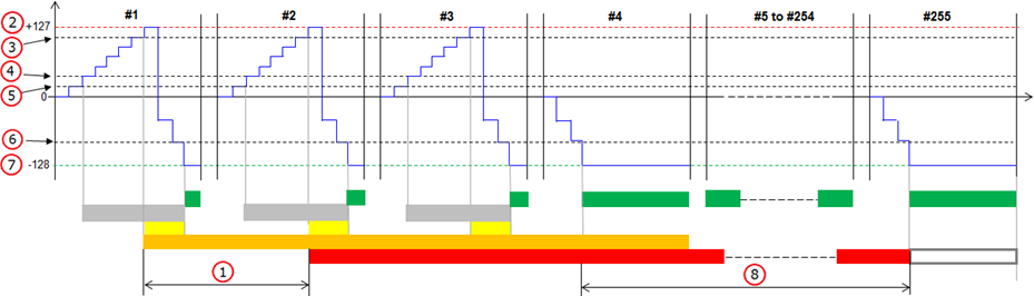
#1 - #255 in the figure represent control module operation cycles.