Note
This tab is only enabled if there are any possible activations available for the control module selected in the Control Module panel.
By using the tab, you can control components in the vehicle from VIDA. This functionality makes it e.g. possible to turn certain features in the vehicle on and off or to run at different levels for functional diagnostics. As an example, the engine coolant fan in a vehicle can be activated to run at 33, 66 or 100 percent.
Note
Note
This tab is only enabled if there are any possible activations available for the control module selected in the Control Module panel.
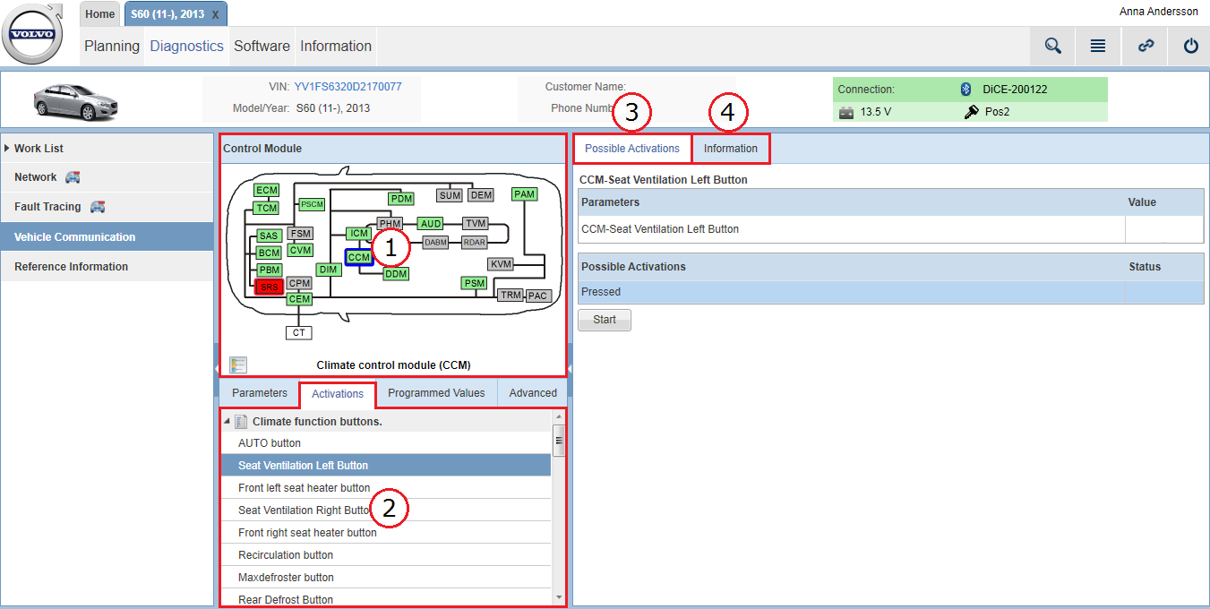
Each area of the page is explained in the subsections below.
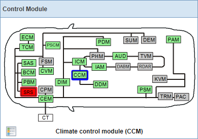
In the Control Module panel, deviations on the vehicle's network communication are presented in a graphic. The graphic reflects the vehicle's network with all control modules' status at the latest readout.
The color of the control modules in the graphic varies depending on status:
|
Color |
Description |
|---|---|
|
Green |
Control module responsive to communication. |
|
Red |
Control module not responsive to communication. |
|
Gray |
Control module not part of the vehicle configuration (it may, however, be in the relevant vehicle model). |
An explanation of the colors is accessed by clicking the  icon.
icon.
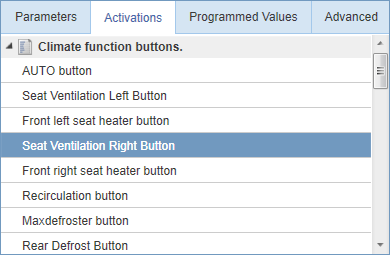
By selecting a control module in the graphic, the list under the tab is populated with all available activation parameters for the selected control module.
In this list, all available activation parameters for the selected control module are listed.
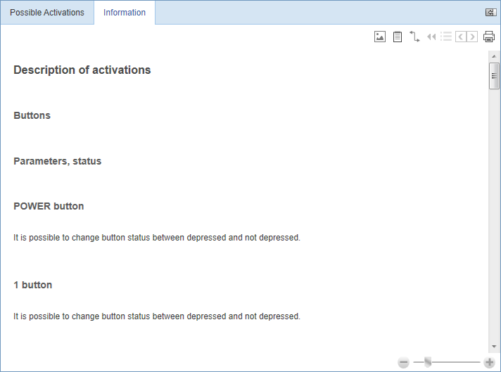
The list is in some cases structured in categories. A  icon is available in some of the category's header. By clicking such an icon, a reference document is opened under the tab on the right-hand side of the screen.
The activation parameter you select from the list is displayed and handled under the tab on the right-hand side of the screen. It is only possible to select one activation parameter at a time.
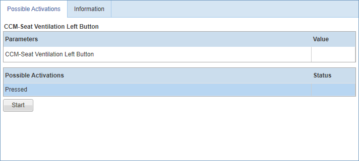
Under this tab, selected activation parameter under the tab is displayed in a table.
The table is structured in two columns:
|
Column |
Description |
|---|---|
|
Parameters |
Name of selected activation parameter. |
|
Value |
Value of selected activation parameter. The values differ from parameter to parameter and can e.g. be "12V", "Pos II" or "On".
A |
The activation action is displayed in the table. The activation is started by clicking the button. Once an activation is started, the button changes name to and you can use the button to stop the activation. When the activation is completed, the status is indicated with either
 (successful) or
  (failed).
Note
Note
It is not possible to select an activation parameter while another activation is in progress.
 icon is displayed if the vehicle is not returning information on selected parameter. Please send an