Collapse all
Expand all
 

DTC Based

On this page, complete lists of possible DTCs for each control unit in the vehicle are available. For each DTC, you can view related CSC and relevant diagnostic procedure documents.

 
Fig. 229: Reference Information - DTC Based

Each area of the page is explained in the subsections below.

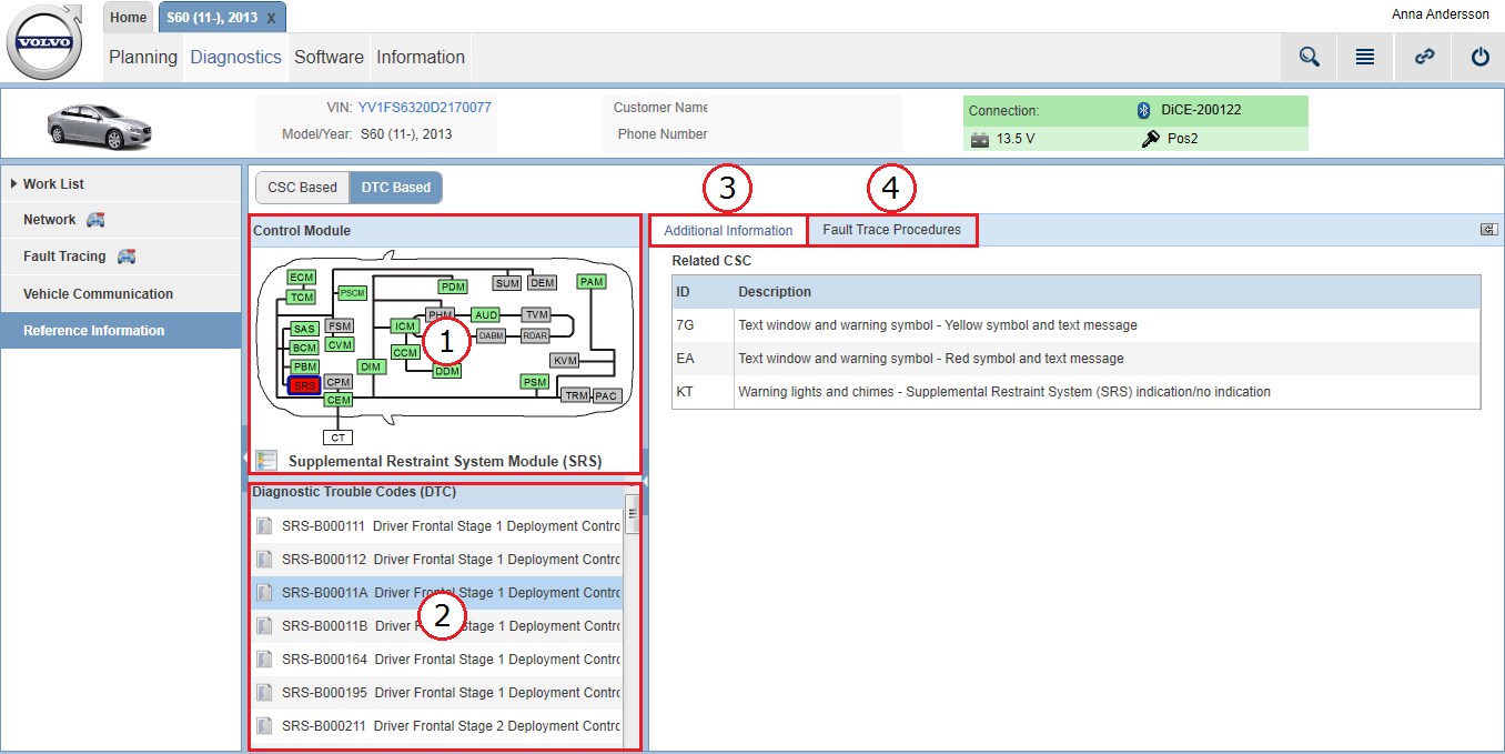
1. Control Module panel

In this panel, deviations on the vehicle's network communication are presented in a graphic. The graphic reflects the vehicle's network with all control modules' status at the latest readout.

 
Fig. 230: The Control Module panel
 

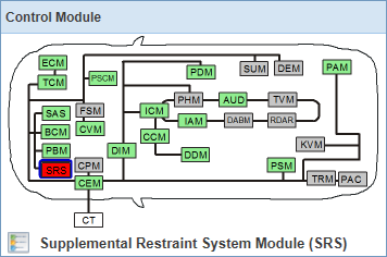
The color of the control modules in the graphic varies depending on status:

Color

Description

Green

Control module responsive to communication.

Red

Control module not responsive to communication.

Gray

Control module not part of the vehicle configuration (it may, however, be in the relevant vehicle model).

An explanation of the colors is accessed by clicking the icon.

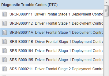
By selecting a control module in the graphic, the list under the Diagnostic Trouble Codes (DTC) tab is populated with all possible DTCs for the selected control module.

2. Diagnostic Trouble Codes (DTC) panel

In this panel, all available DTCs for the selected control module are listed.

 
Fig. 231: The Diagnostic Trouble Codes (DTC) panel

By selecting a DTC from the list, related fault tracing information and procedures are available under the Additional Information and Fault Trace Procedure tabs in the panel on the right-hand side of the screen.

3. Additional Information tab

Under this tab you can see related CSC for the DTC you have selected in the Diagnostic Trouble Codes (DTC) panel.

 
Fig. 232: The Additional Information tab

4. Fault Trace Procedure tab

When selecting a DTC, from the Diagnostic Trouble Codes (DTC) panel, the relevant fault tracing procedure document is presented here.

 
Fig. 233: The Fault Trace Procedure tab

You may also be interested in:

Diagnostics how-to's (D2 and GGD)

Common icons