Note
The page is disabled until the vehicle has been read out. See the article Connected Vehicles for additional information.
To successfully perform a fault tracing, it is essential that all the control modules in the vehicle are connected and respond to the VIDA connection. When a vehicle is read out, some of the control modules may not respond. In this case, you need to correct the issues with the control modules before proceeding with the actual fault tracing.
The Network page helps you identify issues on the network in the vehicle. Such an issue could e.g. be a connection issue, or that the hardware itself is malfunctioning.
This page is divided into four main sections:
Note
Note
The page is disabled until the vehicle has been read out. See the article Connected Vehicles for additional information.
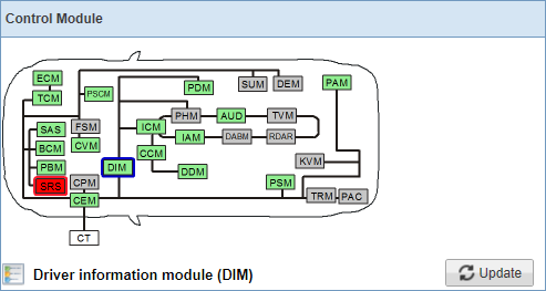
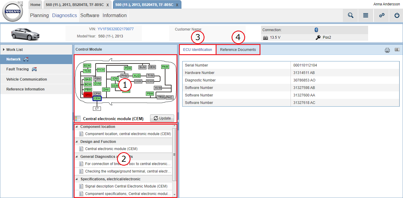
In the Control Module panel, deviations on the vehicle's network communication are presented in a graphic. The graphic reflects the vehicle's network with all control modules' status at the latest readout.
The color of the control modules in the graphic varies depending on status:
|
Color |
Status |
Description |
|---|---|---|
|
Green |
Active |
Control module responsive to communication. |
|
Red |
Not responding |
A control module which is not responsive to communication. A not responding control module is selected by default when entering the Network page. |
|
Gray |
Not present |
Control module is not part of this vehicle's configuration. |
An explanation of the colors is accessed by clicking the  icon. Clicking the button will start a new vehicle readout which will refresh the graphic.
When selecting a control module in the graphic, the following happens:
All related documents for the selected control module are listed in the Reference Information panel.
Identification detail parameters are presented under the tab. These details are only accessible when selecting a control module that is responsive to communication (green).
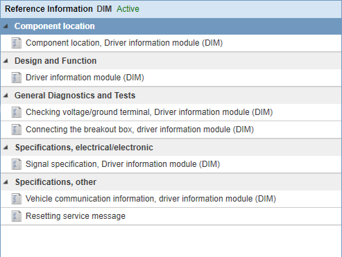
By clicking one of the control modules in the vehicle graphic in the Control Module panel, all related documents are listed in this panel. The name and status of the selected control module is shown in the header.
The documents related to selected control module are structured in the following groups:
Component location
Design and Function
General Diagnostics and Tests
Specifications, electrical/electronic
Specification, other
When selecting a document, it is displayed under the tab.
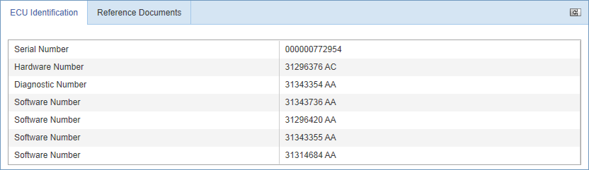
By clicking one of the control modules in the Control Module panel, the following parameters for selected control module can be checked:
Serial Number
Hardware Number
Diagnostic Number
Software Number (one row for each software)
Note
Note
The tab is only accessible for control modules that are responsive to communication (green). These details are not available for control modules that are not responding (red) or not present (gray).
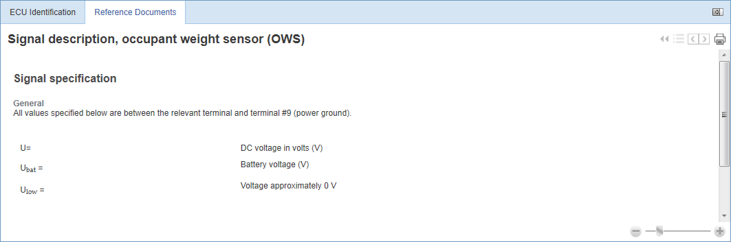
By selecting a document related to a control module in the Reference Information panel, the document is displayed under this tab.
See the article Common icons for instructions on how to use the controls and icons available in the documents.